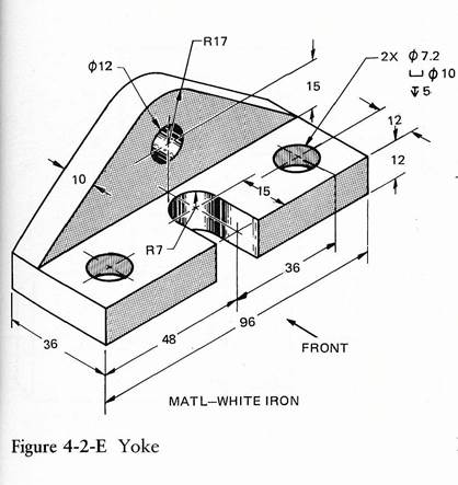
TASK: SECTION the 3 views - Orthographic (Top, Front and Right Side) drawing of the Yoke.
Procedure for Sectioning a Drawing
1. Open your YOKE drawing. This drawing would not typically be sectioned as it is simple enough that the hidden lines are not confusing.
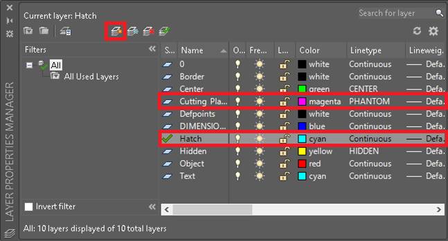
2. Create new layers called Hatch and Cutting Plane – these will be the layers that we will put the Cutting Plane and Section lines on. Change the colours and linetypes as shown below.
1. Open your YOKE drawing. This drawing would not typically be sectioned as it is simple enough that the hidden lines are not confusing.
2. Create new layers called Hatch and Cutting Plane – these will be the layers that we will put the Cutting Plane and Section lines on. Change the colours and linetypes as shown below.
CUTTING PLANE LINE
3. Change to the Cutting Plane layer.
Changing Layers
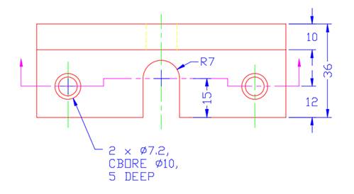
4. The Cutting Plane line is a line that represents where an imaginary cut is made in the object. This is usually done on the Top View. Usually the Front View shows what the object will look like after it is cut.
· On the Top View draw in the Offset Cutting Plane line
· Use the Centerlines to help draw the Cutting Plane line then delete the ones it overlaps.
· The arrows point in the direction you will look at the cut object (Front View).
· To create the arrowheads make a temporary Linear Dimension then Explode it and copy the arrowheads on to the end of the vertical lines.
Changing Layers
4. The Cutting Plane line is a line that represents where an imaginary cut is made in the object. This is usually done on the Top View. Usually the Front View shows what the object will look like after it is cut.
· On the Top View draw in the Offset Cutting Plane line
· Use the Centerlines to help draw the Cutting Plane line then delete the ones it overlaps.
· The arrows point in the direction you will look at the cut object (Front View).
· To create the arrowheads make a temporary Linear Dimension then Explode it and copy the arrowheads on to the end of the vertical lines.
SECTION (Hatch) LINES
5. Change to the Hatch layer .
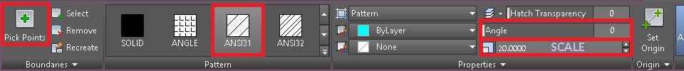
6. Select Hatch from the Draw toolbar and look at the Boundary Hatch settings.
· The Pattern has several hatch patterns to select from. The ANSI31 is the hatch pattern for Cast Iron is what is most commonly used for objects of unknown material also.
· The Angle allows you to adjust the angle of the hatch patterns.
· The Scale needs to be experimented with to get an appropriate spacing of the hatch lines (usually 3 to 5mm).
· Pick Points allows you to pick the area you wish to hatch.
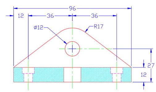
7. Select Pick Points then select the places to hatch on the Front View and right click. This will bring you back to the Boundary Hatch dialog box.
· Select the Preview button to see the results.
· The Scale needs to be adjusted to separate the lines.
· Experiment with different Scale settings.
· Select the Preview button to see the results.
· The Scale needs to be adjusted to separate the lines.
· Experiment with different Scale settings.
SECTION LINES TOO CLOSE!
|
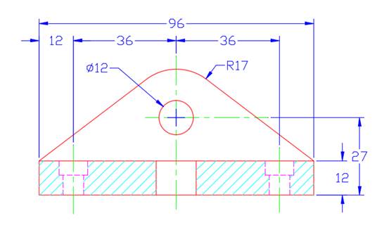
SECTION LINES (SCALE SET TO 20)
|
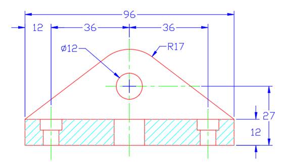
8. The last step is to change the Hidden Lines to Object lines, as they would now no longer be hidden.
9. Fill out the Titleblock appropriately, then printout and hand in for marking.
