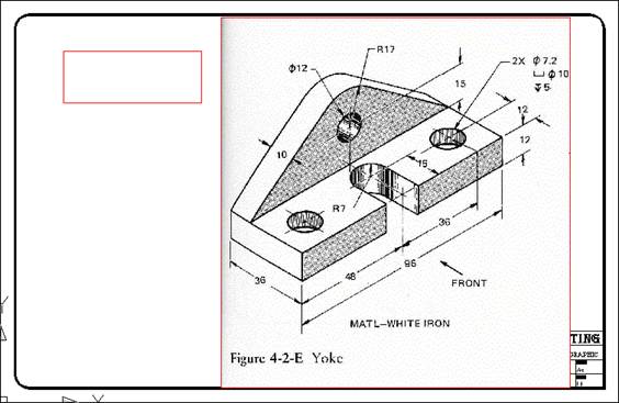
Yoke Tutorial
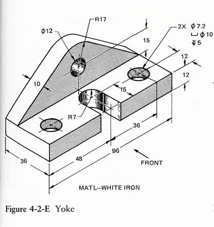
Draw in 3 view Orthographic (Top, Front and Right Side) from the Isometric View
1. Open your Titleblock and Save As YOKE.
2. Most drawing produced and used in industry are Orthographic (Multi-view) drawings.
3. Change to the Object Layer.
2. Most drawing produced and used in industry are Orthographic (Multi-view) drawings.
3. Change to the Object Layer.
|
4. Looking at the YOKE we see that the Top View will have overall dimensions of 96mm long by 36mm wide. Draw the overall sizes of the Top view – guess a starting location, as you will move the views later to center the drawing.
|
|
|
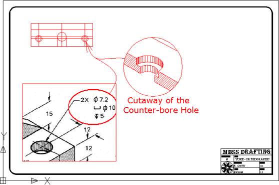
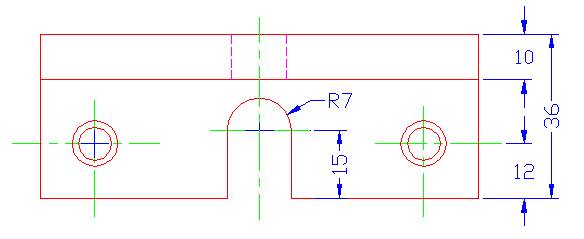
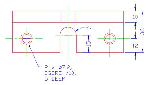
5. Copy (or offset) the lines to locate the circles and draw the circles. Note the outside circles are a counter-bored hole (the outside is a diameter of 10mm and 5mm deep and the through hole is a diameter of 7.2mm).
|
|
|
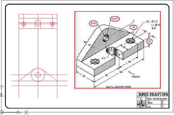
6. Project down the lines from the TOP view for the FRONT view (Orthographic Projection) and then create a horizontal line for the bottom of the FRONT view. Then copy (or offset) that line up to the center of the circle and draw in the centerline and draw the circles. Note: Again the location of the FRONT view is only an approximation and the views will be moved later to center the drawing.
|
|
|
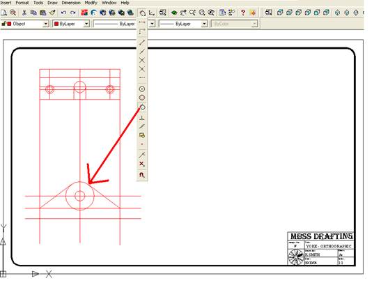
7. Complete the FRONT view using a LINE with the TAN OSNAP .
|
|
|
8. Using the TRIM command clean up the TOP and FRONT views. To use the Trim command 1st pick the object you wish keep, then pick the area you wish to trim. (Note: Instead of 1st picking an object to keep you can right click to pick every object to keep.)
|
|
THE MITER LINE AND ORTHOGRAPHIC PROJECTION
|
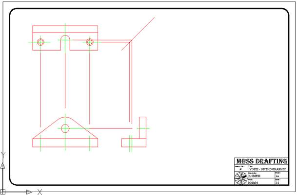
9. Create a Vertical line to indicate the left side of the Right Side view – as before this is an approximation, the views will be moved later to center the drawing. Then draw a line from the bottom of the TOP view to the vertical line.
· This next step is VERY IMPORTANT if you want to become a true drafter. Create what is call a MITER LINE – this 45° line will be used to project (hence Orthographic Projection) lines from the TOP view to the RIGHT SIDE view or visa versa. |
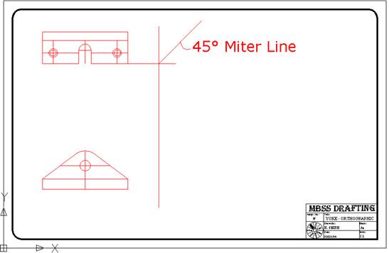
Note carefully that the MITER LINE is drawn from where the lower TOP View line and left RIGHT View line intersect.
|
|
10. Using the MITER LINE and ORTHOGRAPHIC PROJECTION complete the RIGHT SIDE view and TRIM the lines. Do not erase the Miter Line yet you will need it.
|
|
|
CENTER LINES
|
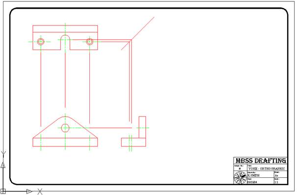
11. Now you can change the CENTERLINES to the correct layer and lengthen them – Centerlines should protrude past the circle or object (they are used to dimension to).
· To change layers click on the lines you wish to change then select the layer you want to change to. · You can also select the Properties icon and then change the layer parameters. This allows you to change many different settings of an object – try it out. · To lengthen the centerlines click on them then select the Grip and move it to the new location – there is no exact amount but look at other drawings to see how they should look. |
|
LINETYPE SCALE
|
12. You will notice that the CENTERLINES are not dashed – you need to set the LTSCALE, that is the Linetype Scale.
· To change the Global Linetype Scale type in LTSCALE at the Command Prompt and change it to 7. Many times you will need to use trial and error to find the best setting for your drawing – try from 0.1 to 25. |
|
HIDDEN LINES
|
13. Draw in the HIDDEN lines next, again project them from the other views.
|
|
|
DIMENSIONING
Basic Dimensioning Rules:
1. Dimension lines are spaced 10mm from the object and 8mm apart from each other. Overall dimensions should be placed outside smaller dimensions and should not cross.
2. Do not duplicate dimensions (one change should be all that is necessary).
· Do not over dimension - only what dimensions are needed to build it.
3. Usually dimension on the view that will be easiest to understand which is usually:
· First on the front view
· Secondly on the top view
· Lastly, if needed, on the side view.
4. Usually dimension:
· Between the views
· To the right side of the view.
5. Avoid dimensioning to or from hidden lines.
|
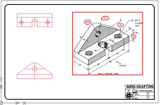
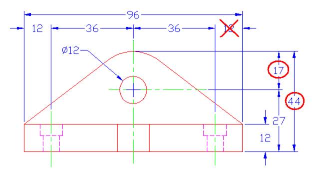
14. Looking at Dimensioning Rule 2 the following Front View dimensioning has problems.· The 12 with the “X” through it would be double dimensioning. Note: Either 12 or 36 dimension could be removed to stop the double dimensioning – the 96 dimension is needed to give the overall size, this helps when constructing the part the builder can get the correct size material without adding up the sizes.
· The circled dimensions are incorrectly done, you should remove the 17 and make it a Radius Dimension and the 44 should only come the centerline of where the radius center-point is. Note: The 44 does give the overall size and can be used as a reference size but usually it is left out when an arc is used. |
|
FRONT VIEW
|
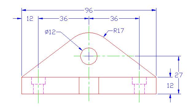
15. To the right is a better way to dimension this object’s Front View.
· Notice following Dimensioning Rule 4 this object is dimensioned between the Front and Top views and to the right side of the view. At times you will need to dimension elsewhere if it makes the dimensioning less confusing. Also, note that the dimensioning is not on the object. · Following Dimensioning Rule 5 the hidden lines are not dimensioned to instead these will be picked up on the Top View. |
|
TOP VIEW
|
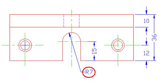
16. Dimensioning the Top View has its own challenges as seen on the right.
· The circled dimensions are okay where they are but they tend to make the dimensioning cluttered and more confusing, in this case it would be better to dimension on the object. The bottom one is the better layout. |
Okay
Better
|
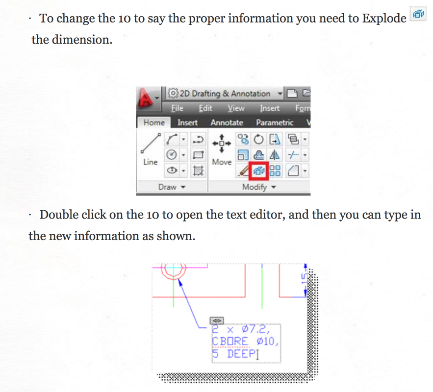
EDITING DIMENSIONS

|
|
|
20. The Right Side view does not require any dimensions as all the sizes are specified on the Front and Top views.
· Move the views so they are balanced on the page. · The last thing to do is center the drawing – to do this make sure to keep the views lined up, therefore move the Front and Top views together when moving sideways and move the Front and Right Side views together when moving up or down. 21. Fill out the Titleblock appropriately, then printout and hand in for marking. |
|
